


Introduction
The field of aircraft design and aerospace engineering has continually sought new technologies and innovations to enhance flight performance, versatility, and efficiency. In this ever-evolving domain, morphing wing technologies (Li et al., Reference Li, Zhao, Da Ronch, Xiang, Drofelnik, Li and Breuker2018; Majid et al., Reference Majid, Jo and Cestino2021; Sivanandi et al., Reference Sivanandi, Gupta and Durai2023) have played a pivotal role, given their potential significant advantages and adaptability in catering to diverse flight missions. Among these technologies, the variable trailing edge cambered wing has garnered substantial interest due to its capability to allow real-time adjustments in the wing’s trailing edge during flight, thus optimizing flight performance (Schlup et al., Reference Schlup, Bishay, McLennan, Barajas, Talebian, Thatcher, Flores, Perez-Norwood, Torres, Kibret and Guzman2021; Bishay et al., Reference Bishay, Kok, Ferrusquilla, Espinoza, Heness, Buendia, Zadoorian, Lacson, Ortiz, Basilio and Olvera2022).
The introduction of variable trailing edge cambered wing technology not only provides the possibility to improve lift and reduce drag characteristics but also imparts greater flexibility to aircraft (Arena et al., Reference Arena, Palumbo, Pecora, Amoroso, Amendola and Dimino2019), allowing seamless transitions between different flight missions (Majid et al., Reference Majid, Jo and Cestino2021; Binwen et al., Reference Binwen, Yu, Zhansen, Zhigang, Shuaishuai and Xiasheng2022). Compared to other variable wing configurations, the variable trailing edge cambered wing presents several distinct advantages. Primarily, it excels in short takeoff and landing (STOL) performance, enabling aircraft to take off and land within constrained runway lengths, which is crucial for aircraft types such as military transport and firefighting planes. Nonetheless, these advantages come with specific challenges and limitations. The design and control of variable cambered wings are relatively complex, which may result in increased manufacturing and maintenance costs (Majid et al., Reference Majid, Jo and Cestino2021; Pecora, Reference Pecora2021). Moreover, achieving real-time adjustments in the wing’s trailing edge requires exact control systems, demanding elevated levels of technical expertise and reliability.
Camber morphing mechanisms can be categorized into structure-based (Chanzy et al., Reference Chanzy and Keane2017; Zhao et al., Reference Zhao, Zou, Jin and Wen2019; Communier et al., Reference Communier, Botez and Wong2020; Kuya et al., Reference Kuya, Ito, Maki and Sawada2021), material-based (Kudva, Reference Kudva2016; Fasel et al., Reference Fasel, Keidel, Baumann, Cavolina, Eichenhofer and Ermanni2020), and hybrid (Tong et al., Reference Tong, Ge, Sun and Liu2014; Vasista et al., Reference Vasista, Riemenschneider, van de Kamp, Monner, Cheung, Wales and Cooper2017; Zhang et al., Reference Zhang, Ge, Zhang, Mo and Zhang2019) mechanisms based on their design features and synthesis methodologies. Structure-based mechanisms rely on the internal structural layout to change the camber of the airfoil. Material-based mechanisms make use of material properties and tools to enhance the elastic nature of the structures. Hybrid mechanisms combine both structure-based and material-based approaches. Structure-based morphing mechanisms can improve the reliability of wing deformation and the richness of function. Nevertheless, it may impact the overall performance of the aircraft and result in higher manufacturing and maintenance costs due to the added complexity and weight of the morphing components. Material-based mechanisms typically utilize intelligent materials that can alter their characteristics, such as shape or stiffness, enabling lightweight design and streamlining wing design and manufacturing compared to traditional structure-based morphing mechanisms. Similar to structure-based morphing mechanisms, material-based mechanisms also possess numerous drawbacks, including limited deformation range, poor durability, and reliability. Hybrid mechanisms combine the advantages of both structure-based and material-based mechanisms and utilize metamaterials (Ma et al., Reference Ma, Cheng, Jang, Luan, Hwang, Rogers, Huang and Zhang2016; Gong et al., Reference Gong, Ren, Sun, Zhang, Du and Xie2022) to prepare morphing wings, affording greater flexibility in achieving desired morphing capabilities. This flexibility enables the design of more intricate and efficient morphing wing configurations. To fulfil the design requirements of lightweighting, high load-bearing stiffness, and superior strength for the wing structure of variable aircraft, we have opted for incorporating a honeycomb structure to fill the wing trailing edge. The honeycomb structure ensures inherent strength and stiffness while concurrently reducing its weight. Moreover, it exhibits outstanding impact resistance, effectively addressing the demands for significant in-plane deformation and high out-of-plane loading (Alderson et al., Reference Alderson, Alderson, Attard, Evans, Gatt, Grima, Miller, Ravirala, Smith and Zied2010; Mizzi et al., Reference Mizzi, Mahdi, Titov, Gatt, Attard, Evans, Grima and Tan2018; Zhong et al., Reference Zhong, Fu, Yin, Xu and Hu2019; Yin et al., Reference Yin, Li, Yang and Li2021a, Reference Yin, Zhao and Li2021b).
With the advancement of technology, researchers believe that intelligent morphing wings not only require the ability to deform but also necessitate monitoring their deformation and controlling the extent of deformation accurately (Basaeri et al., Reference Basaeri, Yousefi-Koma, Zakerzadeh and Mohtasebi2014; Henry et al., Reference Henry, Molinari, Rivas-Padilla and Arrieta2019; Khan et al., Reference Khan, Grigorie, Botez, Mamou and Mébarki2019; Lee et al., Reference Lee and Kim2019; Emad et al., Reference Emad, Mohamed and Fanni2022). Only through such an approach can wings maintain optimal aerodynamic performance in any environment. Accurately controlling the wing deformation presupposes accurately measuring the degree of wing deformation. Additionally, deformation monitoring enables researchers to obtain real-time information on the status of wings, providing a reference for ensuring the safety of wing structures. There are two primary categories of deformation monitoring technologies: non-contact measurement methods and contact measurement methods. Non-contact measurement methods (Li et al., Reference Li, Liang, Guo, Guo, Hu and Tang2014; Kirmse, Reference Kirmse2016) utilize non-contact measurement technologies such as laser, infrared, and ultrasound to acquire deformation information of the wing trailing edge. This method mandates the use of external equipment, and in the presence of obstructions, it cannot accurately obtain wing deformation information, making it impossible to detect wing deformation during aircraft flight. Contact measurement methods (Li et al., Reference Li, Liu and Leng2013; Menghui et al., Reference Menghui and Fang2020; Shin et al., Reference Shin, Ott, Beuken, Ranganathan, Humbert and Bergbreiter2021), on the other hand, acquire deformation information of the wing trailing edge through sensors with the aid of displacement sensors, strain sensors, etc. This method is immune to the external environment; however, it poses stringent requirements on sensor performance and the accuracy of deformation feedback algorithms. The control of wing deformation can be achieved through various methods, such as shape memory alloy (SMA) drive (Akbari et al., Reference Akbari, Sakhaei, Panjwani, Kowsari and Ge2021; Lv et al., Reference Lv, Wang and Lei2021; Lee et al., Reference Lee and Lee2023), mechanism drive (Zhang et al., Reference Zhang, Ge, Zhang, Mo and Zhang2019; Xiao et al., Reference Xiao, Zhao, Xu, Li, Shen, Wang and Zhang2022), and pneumatic drive (Ni et al., Reference Ni, Liao, Li, Zhang, Sun, Chai and Jiang2020; Guo et al., Reference Guo, Feng, Zhu, Zhou and Chen2022). Notably, intelligent drive devices represented by SMAs and polymer (Cebrian et al., Reference Cebrian Carcavilla and Zaki2022) have emerged as popular solutions for novel wing variants due to their inherent characteristics, including lightweight construction, continuous and coordinated deformation, significant relative deformation, noise-free operation, and ease of control. SMA wires demonstrate substantial contraction deformation when subjected to heating, reverting to their initial shape upon cooling (Akbari et al., Reference Akbari, Sakhaei, Panjwani, Kowsari and Ge2021; Lv et al., Reference Lv, Wang and Lei2021; Lee et al., Reference Lee and Lee2023). Consequently, they are deemed suitable for the actuators of large-scale variable aircraft. In comparison with other smart materials, SMA wires boast a higher driving energy density and relatively elevated driving force and strain, along with an exceptionally low mass. The utilization of SMA wires facilitates the substitution of hydraulic actuators with solid-state actuator structures, thereby diminishing the complexity and accident risks associated with aircraft components. Notably, small SMA wires actuators can respond promptly, reducing the weight and installation volume of the actuators and providing a distinct advantage in numerous aerospace applications. However, the integration of these methods to design and manufacture an intelligent wing trailing edge that meets the requirements of load-bearing, continuous deformation, deformation monitoring, and active control is a pressing issue that needs to be addressed.
In this article, we design and fabricate a wing trailing edge structure based on lattice structures (Cheng et al., Reference Cheng, Fan, Yao, Jin, Lv, Lan, Bo, Chen, Zhang, Shen, Wan, Huang and Zhang2023) with non-uniform filling. This can achieve continuous bending deformation while satisfying the load-bearing requirements. To achieve an optimized design that reconciles load-bearing and deformation, we use a genetic algorithm based on neural networks to inversely design the geometric size of the cell units, obtaining the optimal filling method for the lattice structure under the optimized conditions. Additionally, to monitor and actively control the deformation of the trailing edge in real time, we developed a flexible metal sensor based on Constantan-Polyimide (PI), which is based on beam bending deformation theory to provide the strain–displacement relationship for bending deformation. By attaching the sensor to the surface of the trailing edge, we can monitor the deformation of the trailing edge in real time through monitoring changes in the resistance signal of the sensor. To actively control the deformation effect of the trailing edge in real time, we develop a deformation control system based on a proportional-integral-derivative (PID) controller. Utilizing the relationship between current, temperature, and strain of SMA wire, we regulate the SMA current size in reverse through monitoring data of trailing edge deformation and then control the contraction rate of SMA, actively controlling the deformation of the trailing edge. Ultimately, we successfully constructed a closed-loop system for monitoring and actively controlling wing deformation. We have established an experimental platform to evaluate the wing trailing edge. The experimental results demonstrate that the sensor can effectively track and monitor the wing trailing edge’s bending deformation. On this basis, the controller can accurately regulate the bending angle of the wing trailing edge with a deviation of less than 4%.
Trailing edge model and aerodynamic characteristic analysis
Generally, a wing can be divided into three components: the leading edge, the wing box, and the trailing edge, as shown in Figure 1a. For simplification, we selected a symmetric airfoil shape, the NACA0020, with the trailing edge comprising 30% of the entire wing length. In traditional wing designs, bending of the trailing edge is achieved through mechanical transmission resulting in a discontinuous surface (as shown in Figure 1b up). To maintain continuity on the wing surface during the bending of the trailing edge, we utilized SMA actuation to enable continuous deformation (as depicted in Figure 1b bottom). We defined bending angle θ as the angle between a line connecting the vertex of the trailing edge and the midpoint of the airfoil box and a horizontal line (as shown in Figure 1b). Considering that different degrees of deformation have varying effects on aerodynamic characteristics during cruising mode flight without any angle of attack (AoA), we analysed lift coefficient (CL ) and drag coefficient (CD ) generated by trailing edge deformations ranging from 0 to 15° at speeds from Mach number 0.1 to 0.6. A conceptually important lift-to-drag ratio (L/D) was determined for an accurate representation of improvements in aerodynamic performance; higher L/D values indicate better aerodynamic performance for an aircraft. We selected Ansys Fluent 2021 R1 as the calculation software to perform aerodynamic analysis of the airfoil flow field, using SIMPLE’s second-order upwind scheme for solution, and selected Spalart–Allmaras as the turbulence model. The results are shown in Figure 1c-e. Based on the calculations, it can be inferred that NACA0020 needs to maintain a trailing edge deformation of approximately 10° at a cruising speed of 0.3 Ma in order to operate within the optimal lift-to-drag ratio range. Deviating from this ideal deformation angle, either higher or lower, could result in a decline in the lift-to-drag ratio and subsequently impact flight performance. Consequently, we have established a design objective of achieving trailing edge deformations exceeding 10°.
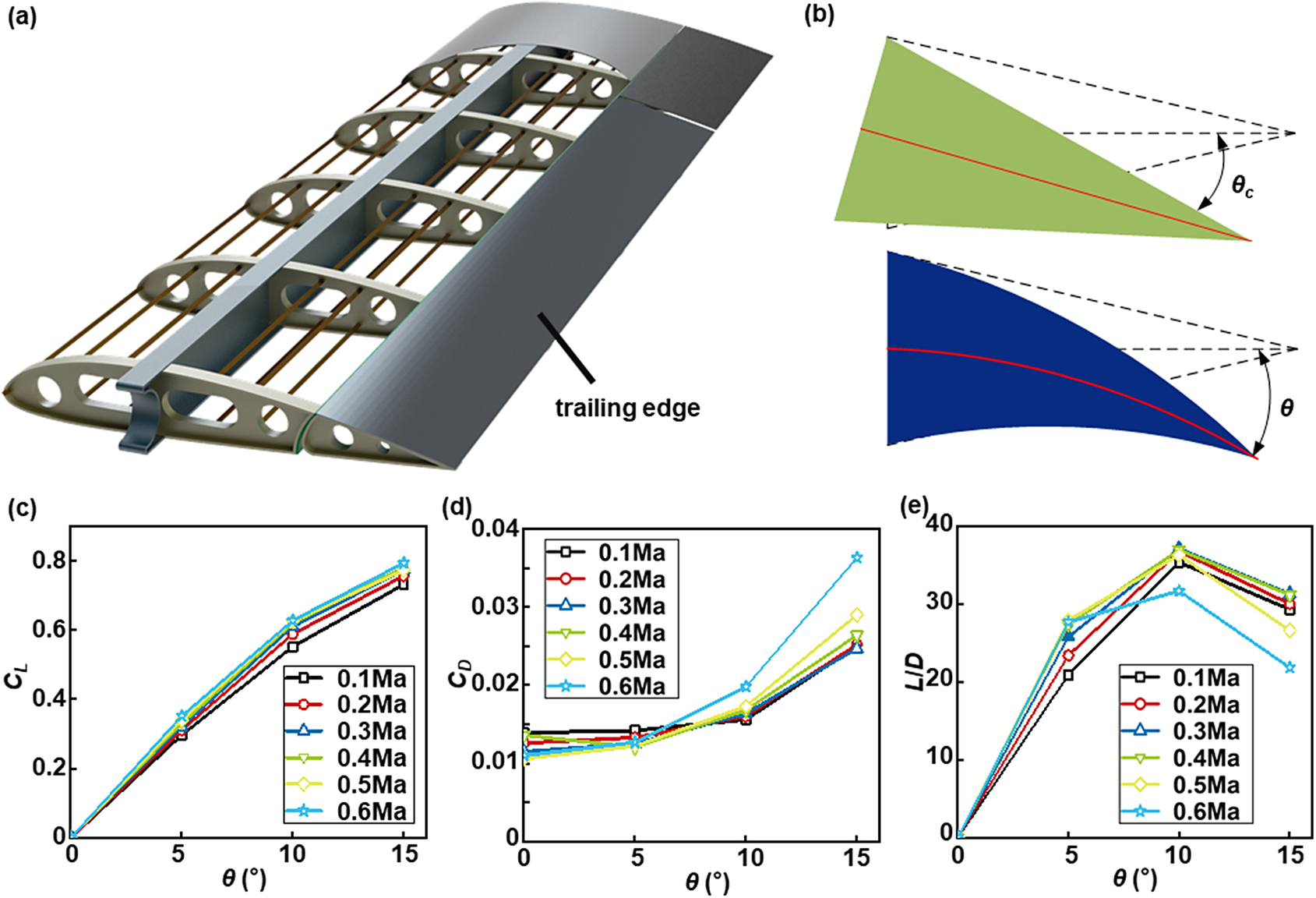
Figure 1. Trailing edge and influence of trailing edge camber on aerodynamic characteristics: (a) schematic diagram of wing trailing edge; (b) schematic diagram of conventional trailing edge deflection (up, green) and camber morphing trailing edge (bottom, blue). The curvature of the upper and lower surfaces varies continuously and is related to the parameter θ. To facilitate the elaboration of the problem, the single parameter θ is used to represent the degree of trailing edge bending; (c) lift coefficient under different trailing edge deformation angles and speeds; (d) drag coefficient under different trailing edge deformation angles and speeds; (e) lift drag ratio under different trailing edge deformation angles and speeds.
The non-uniform gradient filling strategy for the trailing edge
Inverse design algorithm
The NACA0020 airfoil is characterized by its symmetry, allowing us to consider the trailing edge structure as an almost perfect isosceles triangle. The three-layer heterogeneous beam structure exhibits distinctive mechanical coupling characteristics; we divide the trailing edge into deformable structures in the upper and lower layers and a driving (contracting) structure in the middle layer. When the elastic modulus E 1 of the upper layer exceeds that of the lower layer E 3, internal contraction in the middle layer induces deflection of the entire structure. This deformation mechanism enables downward bending deformation of the wing’s trailing edge. To achieve continuous variation in bending curvature while meeting design targets for bending angles, it becomes necessary to inverse design both upper and lower layers’ elastic moduli. To accomplish this goal, we employ a genetic algorithm based on backpropagation neural network (BPNN) (Figure 2a). Numerous training sets are necessary for the training of a BPNN. In this study, the input and output sets of the BPNN are the geometric parameters of the filling structure and the cross-sectional profile of the wing, respectively. Due to the high cost of obtaining the training data experimentally, we used finite element method (FEM) results instead. In order to accurately simulate the bending effect of the wing trailing edge, we have constrained a portion away from the wingtip and set the thermal expansion coefficient of the intermediate layer material to a negative value. When subjected to a temperature load, the intermediate layer material contracts with increasing temperature, causing the entire structure to bend downward. The chosen elements for analysis are solid elements (C3D8R), and the solver is standard (Figure 2b). To maintain the consistency of different structural equivalent elastic modulus control methods and the overall coordination of the filling structure, we opted to modify the geometric parameters (unit wall thickness t) of the filling structure to change its equivalent elastic modulus. The wing trailing edge structure is derived from an array of lattice unit cells. Consequently, the equivalent modulus in various regions is intricately associated with the wall thickness of the unit cells (Figure 2c).

Figure 2. The non-uniform gradient filling scheme for the trailing edge: (a) schematic representing the proposed inverse design algorithm-based genetic algorithm; (b) the finite element model of the wing trailing edge (taking a chiral structure as an example); (c) the relationship between structural parameters and equivalent modulus obtained by the theoretical method. From left to right: t and L of chiral structure, t and β of quadrangular structure, and t and α of four-pointed star structure; (d) camber morphing trailing edge of wing filled with different structures: 6-connected chiral structure, 4-connected chiral structure, and horseshoe structure.
By adjusting the wall thickness of the cells within a range of 0.5-2 mm, we can regulate the equivalent modulus of the structure, thereby modifying the ratio of the equivalent modulus between the upper and lower sections of the structure. This manipulation accomplishes the goal of achieving diverse bending effects under identical driving forces. Consequently, we created 2000 sets of wing models exhibiting diverse levels of deformation. By establishing a correlation between lattice structure parameters and trailing edge profile using a BPNN, we achieved the goal of predicting the degree of bending deformation at the trailing edge based on lattice structure parameters.
Honeycomb structure
In order to achieve greater deformation and lighter trailing edge structure while maintaining overall structural stiffness, we have selected various honeycomb lattice structures for investigation, namely, the 6-connected chiral structure, the 4-connected chiral structure, and the horseshoe structure. The chiral honeycomb structure with six ligaments exhibits tensile expansion characteristics and is composed of hollow cylindrical nodes connected by tangent strips. Its mechanical performance is influenced by factors such as the number of strips and the wall thickness. Due to the unique characteristics of honeycomb structures, when studying their in-plane mechanical performance, they are typically simplified as two-dimensional structures. This simplification significantly reduces the complexity of theoretical derivations. Therefore, when studying the in-plane equivalent elastic modulus of honeycomb structures, they can be regarded as two-dimensional structures composed of beams. Based on the small deformation assumption, different formulas for the equivalent elastic modulus of various structures can be derived. The equation used to calculate its equivalent elastic modulus is as follows (Alderson et al., Reference Alderson, Alderson, Attard, Evans, Gatt, Grima, Miller, Ravirala, Smith and Zied2010):
 $$\begin{align}E=\frac{\sqrt{3}{E}_st{}^3}{r^2\cdot L}\end{align}$$
where r is the outer radius of the hollow cylindrical node, L is the length of the ligament connecting adjacent nodes, t is the wall thickness, and Es is the elastic modulus of the material used.
The other two honeycomb structures are dominated by bending deformation, and the equivalent elastic modulus calculation equations are (Mizzi et al., Reference Mizzi, Mahdi, Titov, Gatt, Attard, Evans, Grima and Tan2018; Zhong et al., Reference Zhong, Fu, Yin, Xu and Hu2019; Yin et al., Reference Yin, Li, Yang and Li2021a, Reference Yin, Zhao and Li2021b) as follows: Equation (2) is the calculation formula of equivalent elastic modulus of 4-connected chiral structure,
 $$\begin{align}E=\frac{8{E}_s{t}^3}{4{t}^2L{\sin}^2\beta +{L}^3{\cos}^3\beta }\end{align}$$
 $$\begin{align}E=\frac{2\sqrt{3}{E}_s{t}^3\left(\alpha -\sin \alpha \right)}{3{r}^3\left[14{\alpha}^2+4\left({\alpha}^2+4\right)\cos \alpha -4\alpha \left(7\sin \alpha +\sin 2\alpha \right)-13\cos 2\alpha -3\right]}\end{align}$$
where t is the wall thickness, L is the length of the ligament connecting adjacent nodes, and β is the angle between the square node and the ligament. Equation (3) is the calculation formula of equivalent elastic modulus of horseshoe structure, where t is the wall thickness, L is the length of the unit cell, α is the arc angle of circular arcs, and r is the radius of circular arcs. Their quantitative relationship is L = 4r * sin(α/2).
As shown in Figure 2c, we systematically investigated the correlation between structural parameters and equivalent modulus for three different structures, from left to right: chiral structure (t and L), rectangular structure (t and β), and four-pointed star structure (t and α). By solely adjusting the unit wall thickness t, a wide range of elastic moduli can be achieved for all three structures. This demonstrates the feasibility of utilizing a honeycomb lattice structure to fill the trailing edge of the wing, enabling continuous bending deformation. Figure 2d illustrates the wing’s trailing edge structure obtained through inverse design using a genetic algorithm, clearly showing that the upper structural unit has a greater thickness than the lower one.
Experiment and FEM of wing trailing edge
We employed stereolithography 3D printing technology to fabricate the trailing edge structures acquired through the inverse design method. The specific 3D printing parameters are as follows: layer thickness, 0.05 mm; exposure time, 10 s; bottom exposure time, 50 s; lift height, 5 mm; and scanning speed, 50 mm/s. To secure the SMA wire, the printed structure incorporates hollow channels in its middle layer. The SMA wire is threaded through pre-drilled holes and affixed using terminal connectors, anchoring the entire trailing edge at the end of a metal wing box, as depicted in Figure 3a. A magnified view on the right side illustrates how the SMA wire is secured and connected to a power source. Upon applying power, contraction of the SMA wire occurs. Due to the higher elasticity modulus of the upper layer compared to that of lower layers, when contraction takes place in the middle layer, it induces downward bending deformation of the trailing edge. Furthermore, we simulated this bending deformation process utilizing FEM. The experimental and FEM results are shown in Figure 3b. From the figure, it can be observed that there is a noticeable bending deformation near the wingtip. Therefore, sensors will also be placed in this region. The bending deformations of trailing edges filled with three different honeycombs all exceeded 10°; however, there is a noticeable disparity in performance for chiral structures where most of their bending occurred at their front section. This can be attributed to an increased number of ligaments enhancing structural resistance against bending. In addition, the bending angles obtained from FEM are more significant than the experimental results, which are attributed to printing errors. In addition, the angles of rear edge curvature are not limited to the 10° specified in the previous text, and excessive bending can result in a decrease in the lift-to-drag ratio of the wing. Therefore, more intelligent control methods are required to make the rear edge curvature adjustable, allowing for varying degrees of bending in different operating environments and maximizing the aerodynamic efficiency of the wing to maintain optimal performance.

Figure 3. Comparison between FEM and experimental results: (a) FEM (up) and experimental platform (bottom); the image in the red dotted line is the specific connection type of SMA; (b) comparison of experimental and FEM results under different filled structures.
Deformation feedback and active control
In order to accurately control the bending angle of the trailing edge, we need to perform real-time detection of the bending angle and adjust the driving force at the actuator level based on its magnitude. When the bending angle is too large, we reduce the contraction rate of the SMA wire; when it is too small, we increase the contraction rate. Therefore, we have developed a feedback and control system for trailing edge bending deformation based on metal-based flexible sensors, as shown in Figure 4a.

Figure 4. Measurement method of trailing edge bending angle and sensor preparation: (a) schematic of sensor position, data transmission method, and active control method for bending angle; (b) preparation of flexible sensors based on constantan and PI, and CAD images (up) and physical photographs of sensors (bottom); (c) the relationship between node coordinates and resistance change rate; (d) schematic diagram of real displacement calculation method.
Transformative feedback system
In order to monitor the bending angle of the trailing edge in real time, we have designed and fabricated a flexible metal sensor. The sensor structure is shown in Figure 4b, with copper as the sensing unit and PI as the substrate material. The overall thickness is 300 μm, with an upper layer PI thickness of 25 μm and a lower layer PI thickness of 275 μm. Seven sensing units are integrated together to form a multichannel metal-based flexible sensor. The sensor can be connected to a processor through standard connectors. By attaching the flexible sensor to the surface of the wing trailing edge, it bends along with any deformation of the trailing edge. As the sensing units deviate from their neutral position, this bending causes changes in resistance within each sensing unit, as shown in Figure 4c. The relationship between changes in resistance values of the sensing units and strain is represented by Equation 4.
 $$\begin{align}\frac{\Delta R}{R}= K\varepsilon\end{align}$$
where ΔR represents the change in resistance of the sensing unit, R is the initial resistance value of the sensing unit, K is a constant coefficient obtained through calibration of the sensor, and ε is the average strain at the location where the sensor is installed.
In order to accurately determine the value of coefficient K, we conducted calibration on our homemade sensors. By comparing with commercial strain gauges, we obtained a sensor coefficient K = 2.13. From the test results, it can be seen that our sensors have equally accurate testing results and can detect extremely small strain changes. Due to their thin thickness, multichannel sensors can still be considered as experiencing small deformations within a small range even when undergoing significant overall bending deformation, thus satisfying the assumption of small deformations. Although there are only seven channels in the sensor for testing positions, by fitting and processing the sensor data, strain values at any position can be obtained. By dividing the entire sensor into countless micro-segments according to Equation 5, the rotation angle of any micro-segment can be calculated based on strain measurements (see Equation 6).
 $$\begin{align}\ \,\kern1.2pt\varepsilon =\frac{S_1-{S}_0}{S_0}=\frac{h}{2\rho}=\frac{h}{2}\cdot \frac{{\mathrm{d}}^2\omega }{\mathrm{d}{x}^2}\qquad\end{align}$$
 $$\begin{align} \begin{array}{l}\displaystyle{\theta}_{i+1}={\int}_{\!\!\!xi}^x\frac{{\mathrm{d}}^2\omega }{\mathrm{d}{x}^2}\mathrm{d}x={\int}_{\!\!\!x_i}^{x_{i+1}}\frac{1}{\rho_{i+1}}\mathrm{d}x+C\\[3pt] \displaystyle{}{\theta}_{i+1}=\frac{1}{\rho_{i+1}}\left({x}_{i+1}-{x}_i\right)=\frac{\Delta L}{\rho_{i+1}}\end{array}\end{align}$$
where ε is the average strain at the sensing unit, S 1 is the length of the sensing unit layer after bending deformation, S 0 is the initial length, h is the distance from the sensing unit layer to the neutral plane, ρ is the curvature radius, θ is the relative rotation angle, and ΔL is the length of the unit.
By considering the length and curvature of a micro-segment, we can determine the local torsion of this segment and subsequently compute the local displacement of its endpoints using Equation 7.
 $$\begin{align} \begin{array}{l}\displaystyle{x}_i={\rho}_{\mathrm{i}}\sin \left({\theta}_{\mathrm{i}}\right)\\ \displaystyle{}{y}_i={\rho}_{\mathrm{i}}\left(1-\cos \left({\theta}_{\mathrm{i}}\right)\right)\end{array}\end{align}$$
where x and y are the relative horizontal and vertical coordinates of the node, respectively.
As the sensor end remains fixed, both displacement and torsion are constrained to zero at this point. Incorporating this boundary condition, we can iteratively calculate the accurate displacement at any position using Equation 7, thereby enabling a more precise estimation of torsion magnitude at the trailing edge.
 $$\begin{align} \begin{array}{l}\displaystyle{x}_{r_i}={x}_i\cos {\theta}_{r_{i-1}}-{z}_i\sin {\theta}_{r_{i-1}}+{x}_{r_{i-1}}\\ \displaystyle{}{y}_{r_i}={y}_i\sin {\theta}_{r_{i-1}}+{y}_i\cos {\theta}_{r_{i-1}}+{y}_{r_{i-1}}\end{array}\end{align}$$
where xr
and yr
are the real horizontal and vertical coordinates of the node, respectively. ${\theta}_{r_i}={\theta}_{r_{i\hbox{-} 1}}+{\theta}_{i-1}$
is the real rotation angle.
${\theta}_{r_i}={\theta}_{r_{i\hbox{-} 1}}+{\theta}_{i-1}$
is the real rotation angle.
Active control system for bending deformation
In order to accurately control the bending angle, it is necessary to study the properties of SMA wire. We conducted tensile tests on SMA wires with a diameter of 0.3 mm. The stress corresponding to the start of martensitic phase transformation was measured at 393 MPa, the tensile strength is 564 MPa, and the fracture strain is 5.6%. The SMA wires undergo phase transition due to temperature rise, leading to wire shrinkage. The length and diameter of the SMA wire are 100 and 0.3 mm, respectively. To investigate the correlation between temperature and current size in SMA, we maintained a constant voltage of 10 V while gradually increasing current by increments of 0.2 A. The temperature of the metal wire was measured after each increase using an infrared thermometer. The non-linear relationship between temperature and current is illustrated in Figure 5h. Simultaneously, we recorded the variations in the length of the SMA wire throughout the entire experimental procedure and fitted the experimental data to obtain the relationship between temperature and current, as well as length and current, which is illustrated in Figure 5.

Figure 5. The relationship between the temperature of the SMA metal wire and the magnitude of current and strain: (a–f) thermal imaging map; (g) the mechanical properties of the SMA wire; (h) the relationship between the temperature and the current; (i) the relationship between the strain and the temperature.
By designing the trailing edge structure and conducting a comprehensive analysis of the performance of SMA wires, we have successfully developed an advanced active wing morphing control system, as shown in Figure 6a. The complete system comprises a non-uniformly filled trailing edge, a flexible metal sensor, a pulse width modulation (PWM) system, a direct-current (DC) power supply, and upper computer software. The trailing edge structure of the wing is manufactured using photopolymerization 3D printing technology and connected to the metal wing box through a mortise and tenon joint structure, ensuring a fixed constraint at the connection point. Two multichannel metal-based sensors are securely fastened to the upper and lower surfaces of the wing, near the wing’s tip, using snap fasteners. The snap-fastening method ensures that the sensors do not impact the wing’s bending, as there is mutual sliding between the sensors and the wing. A PWM system is employed to control the on/off state of the current, thereby regulating the temperature of the SMA wire. When a current passes through the SMA, it undergoes heating due to the Joule effect, leading to contraction deformation. Upon power-off, the temperature of the SMA wire decreases, restoring its initial shape. The upper computer software is a program independently developed based on the Python language. The signal collector uploads real-time signals from the sensors during the deformation process to the upper computer. The built-in calculation program in the upper computer rapidly computes the post-deformation contour (node coordinates) of the wing’s trailing edge. By modifying the node coordinates, real-time feedback of the wing’s trailing edge deformation is achieved. Therefore, the trailing edge bending angle at any given moment is known. When a specific angle adjustment of the trailing edge is required, the corresponding angle value is simply uploaded to the upper computer software. The system detects and compares the deformation angle with the input value; the corresponding value is obtained by the relevant PID algorithm program. By applying different duty cycles of PWM waves to the metal oxide semiconductor field-effect transistor (MOSFET) gate electrode at a 10 V voltage, it becomes possible to modulate current passing through the SMA wire and thereby regulate wing bending deformation.

Figure 6. Experimental platform and results of wing bending control: (a) experimental platform; (b) experimental results (up) and feedback results (bottom) obtained from sensor calculations: 0°, 5°, and 10°.
When the system is powered on, the initial position is not horizontal due to the influence of gravity. Therefore, the first step is to zero out the detected deformation angle using the program. Afterwards, a desired deformation angle is sent to the control board via a mobile phone Bluetooth app. The control board then generates a corresponding PWM waveform to heat the SMA, driving the structure to deform accordingly. The deformation feedback section continuously transmits real-time deformation data to the host computer, enabling the visualization of the deformation. Simultaneously, deformation feedback information is sent back to the controller to facilitate a closed-loop process. Starting from 0° and increasing in 5° increments, a target angle is sent at each step, and the final deformation angle is recorded, as shown in Figure 6b. The figures demonstrate a high degree of alignment between the actual deformation angle and the desired angle, thereby confirming the feasibility of the entire system.
Conclusion
In this study, a non-uniform lattice-filled trailing edge structure was designed and fabricated. To actively control its deformation angle, a flexible metal sensor was developed, enabling the development of a deformation feedback and active control system for the trailing edge structure. The aerodynamic characteristics of wings with different variable curvature trailing edges were analysed, determining the optimal bending angle of 10°. Based on this finding, an inverse design method using genetic algorithms was employed to determine the specific size of the lattice used to fill the trailing edge, ensuring continuous bending while achieving angles greater than 10°. We have developed a Constantan-PI flexible metal sensor that provides a resistance–strain displacement correlation relationship. This sensor is attached to the surface of the trailing edge structure, allowing real-time feedback for obtaining a digital model of its deformation. Furthermore, we systematically studied the relationship between the current temperature shrinkage rate of SMA metal wire and achieved active control of the bending angle using the PWM system. This work introduces novel ideas and methods for intelligent variant structures’ development.
Data availability statement
The data that support the findings of this study are available from the corresponding author upon reasonable request.
Funding statement
This work was supported by the National Key R&D Program of China (2022YFB3805700).
Competing interest
The authors declare none.
Author contribution
The manuscript was written through the contributions of all authors. All authors have given approval to the final version of the manuscript. X. G. conceived the research idea and supervised the overall project. X. L. and L. S. prepared the testing samples and conducted mechanical and functional experiments. X. L. and Y. P. conducted the finite element analysis of the structures. L. S. and Y. P. helped analyse the experimental data and revise the manuscript.


 Open access