1 Introduction
In high-power laser systems, intensity and phase fluctuations in the laser beam induced by dust, defects on optical elements and so on[Reference Aikens, Wolfe and Lawson1], grow rapidly during propagation in the laser media, and further lead to beam filamentation. This physical phenomenon is known as small-scale self-focusing (SSSF). The SSSF effect will limit the useful power of laser systems, either by creating damage or by limiting the focusability of laser beam, and is therefore a principal restriction in the realization of high-energy/power performance[Reference Bespalov and Talanov2–Reference Chen, Li, Chen, Pu, Zhang and Zhu6]. Previous research showed that the SSSF effect could be suppressed by minimizing the accumulated nonlinear phase as well as by reducing spatial noise[Reference Mironov, Lozhkarev, Luchinin, Shaykin and Khazanov7]. In the latter case, a traditional pinhole spatial filter is usually employed to suppress the SSSF effect by filtering most medium and high frequencies in the laser beam[Reference Hunt, Glaze, Simmons and Renard8, Reference Garanin, Epatko, L’vov, Serov and Sukharev9], although it is limited by the huge size, high cost for the vacuum environment and the pinhole-closure effect induced by the high focal intensity[Reference Pearlman and Anthes10]. To solve these problems, angular filters based on volume Bragg gratings (VBGs) with excellent Bragg selectivity, high diffraction efficiency and high damage threshold have been proposed in recent years[Reference Efimov, Glebov, Glebova, Richardson and Smirnov11–Reference Zhang, Yuan, Wu, Feng, Zou and Zhang13]. These can improve the uniformity of the laser beam in the near field, reduce the system scale and avoid the pinhole-closure effect[Reference Ludman, Riccobono, Caulfield, Fournier, Semenova, Reingand, Hemmer and Shahriar14]. However, the traditional angular filter cannot be used in plug-and-play schemes since the output beam is efficiently diffracted and the optical axis of the output beam is deflected with respect to the incident beam through the VBGs, thus introducing difficulties in the alignment of laser systems. Moreover, all medium and high frequencies above the cut-off frequency will be cleaned up in the traditional angular filter, and too great a loss of these frequencies in the filtering process may cause a decrease in the effective fill factor in the amplifier, leading to a reduction in the energy extraction efficiency for laser amplification.
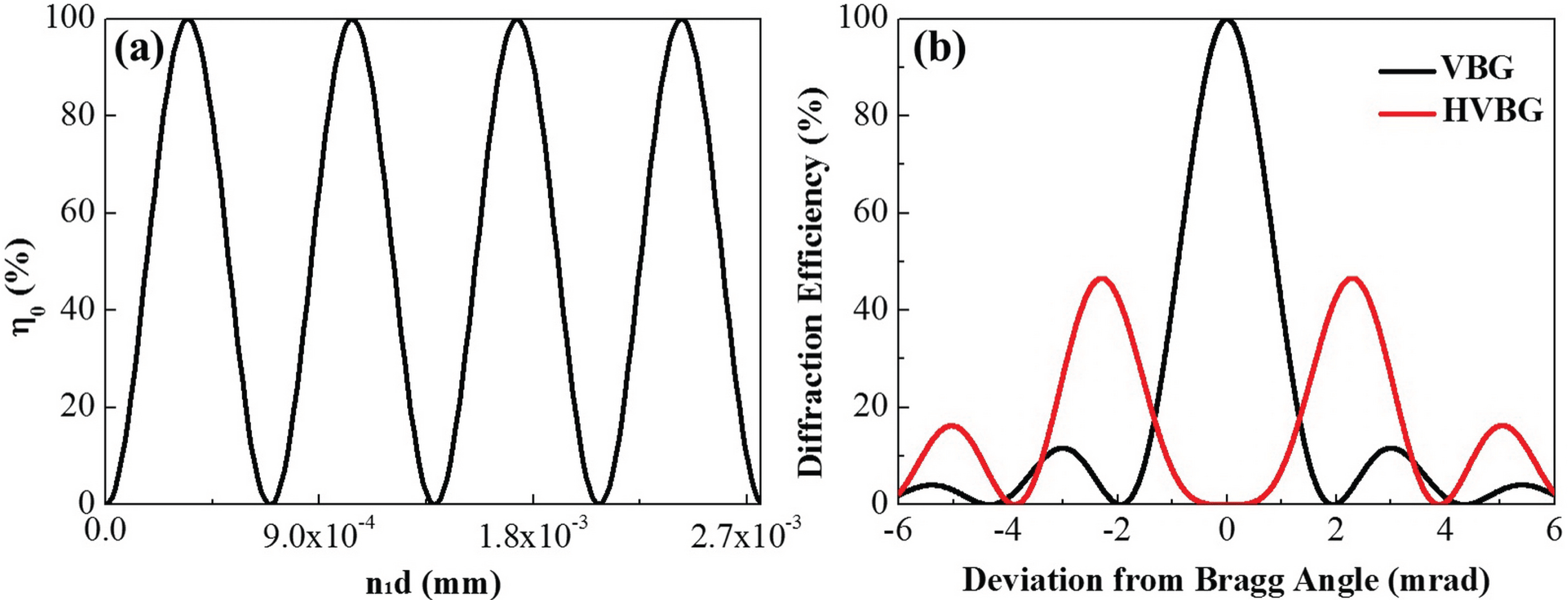
Figure 1. (a) Dependence of the central diffraction efficiency of the VBG on the product of the refractive index modulation and grating thickness; (b) angular selectivity of the VBG and HVBG.
To solve these problems, a band-stop angular filter (BSF) based on hump volume Bragg gratings (HVBGs) was proposed. Previous research has shown that the initiation of beam filamentation is due to the spatial frequencies which have the greatest nonlinear gain in the laser beam[Reference Bespalov and Talanov2, Reference Campillo, Shapiro and Suydam15]. For high-power laser systems, a specific range of medium–high frequencies (MHFs) around the millimeter scale possesses the greatest nonlinear gain[Reference Bliss, Speck, Holzrichter and Erkkila16–Reference Lawson, Wolfe, Trenholme, Aikens and English18]. Therefore, we propose to effectively suppress the SSSF effect by filtering only the MHFs around the millimeter scale in a high-power laser system.
As a novel diffraction element, the angular selectivity of HVBGs is a hump-like function with two maximum diffraction peaks symmetrically located on both sides of the Bragg condition[Reference Gao19]. When the laser beam is incident on the HVBG at the Bragg condition, diffraction occurs only for specific spatial frequencies in the beam at the two diffraction peaks, and almost all other spatial frequencies are transmitted through the HVBG, thus realizing the separation of specific MHFs and other spatial frequencies. Moreover, the filtered transmitted beam of the HVBG is coaxial with the incident beam, thus overcoming the inherent shortcomings of the traditional angular filter and allowing its use in plug-and-play schemes. When HVBGs are inserted in the laser path, the MHFs are continuously diffracted and suppressed. Therefore, band-stop filtering based on HVBGs can control the growth of those spatial frequencies with the larger nonlinear gain and suppress the SSSF, which ensures safe operation of the laser system.
In this Letter, a BSF based on HVBGs is proposed. Suppression of SSSF with the BSF in a two-stage amplifier laser system is simulated and the filtering performance is studied by means of the near-field modulation (
![]() $M$
)[Reference Sun, Peng, Liu, Xu, Zhao, Wang and Fu20] and power spectral density (PSD)[Reference Elson and Bennett21].
$M$
)[Reference Sun, Peng, Liu, Xu, Zhao, Wang and Fu20] and power spectral density (PSD)[Reference Elson and Bennett21].
2 Formation conditions and filtering principle of HVBGs
According to the coupled-wave theory[Reference Kogelnik22], the angular selectivity of a lossless untilted transmitting VBG can be described as
where
![]() $n_{1}$
is the refractive index modulation,
$n_{1}$
is the refractive index modulation,
![]() $d$
is the grating thickness,
$d$
is the grating thickness,
![]() $\unicode[STIX]{x1D706}$
and
$\unicode[STIX]{x1D706}$
and
![]() $\unicode[STIX]{x1D703}$
are the wavelength and incidence angle of the incident beam inside the grating, respectively, and
$\unicode[STIX]{x1D703}$
are the wavelength and incidence angle of the incident beam inside the grating, respectively, and
![]() $\unicode[STIX]{x0394}\unicode[STIX]{x1D703}$
is the angular deviation from the Bragg angle inside the grating. When the Bragg condition (
$\unicode[STIX]{x0394}\unicode[STIX]{x1D703}$
is the angular deviation from the Bragg angle inside the grating. When the Bragg condition (
![]() $\unicode[STIX]{x0394}\unicode[STIX]{x1D703}=0$
) is satisfied, the diffraction efficiency can be simplified to
$\unicode[STIX]{x0394}\unicode[STIX]{x1D703}=0$
) is satisfied, the diffraction efficiency can be simplified to
where
![]() $\unicode[STIX]{x1D702}_{0}$
is the central diffraction efficiency of the VBG,
$\unicode[STIX]{x1D702}_{0}$
is the central diffraction efficiency of the VBG,
![]() $\unicode[STIX]{x1D703}_{0}=\text{arcsin}(\unicode[STIX]{x1D706}/2\unicode[STIX]{x1D6EC})$
is the Bragg angle, and
$\unicode[STIX]{x1D703}_{0}=\text{arcsin}(\unicode[STIX]{x1D706}/2\unicode[STIX]{x1D6EC})$
is the Bragg angle, and
![]() $\unicode[STIX]{x1D6EC}$
is the grating period. It can be concluded from Equation (2) that values of
$\unicode[STIX]{x1D6EC}$
is the grating period. It can be concluded from Equation (2) that values of
![]() $\unicode[STIX]{x1D702}_{0}$
can be achieved from 0 to 100% by accurately adjusting the value of
$\unicode[STIX]{x1D702}_{0}$
can be achieved from 0 to 100% by accurately adjusting the value of
![]() $n_{1}d$
, as shown in Figure 1(a). When
$n_{1}d$
, as shown in Figure 1(a). When
![]() $\unicode[STIX]{x1D702}_{0}=100\%$
, the traditional single-peak VBG is obtained, while the single-peak VBG turns into an HVBG at
$\unicode[STIX]{x1D702}_{0}=100\%$
, the traditional single-peak VBG is obtained, while the single-peak VBG turns into an HVBG at
![]() $\unicode[STIX]{x1D702}_{0}=0$
, as shown in Figure 1(b). Compared with the traditional single-peak VBG, the diffraction efficiency of HVBGs at the Bragg condition is zero, while the maximum diffraction is symmetrically located on either side of the Bragg condition.
$\unicode[STIX]{x1D702}_{0}=0$
, as shown in Figure 1(b). Compared with the traditional single-peak VBG, the diffraction efficiency of HVBGs at the Bragg condition is zero, while the maximum diffraction is symmetrically located on either side of the Bragg condition.
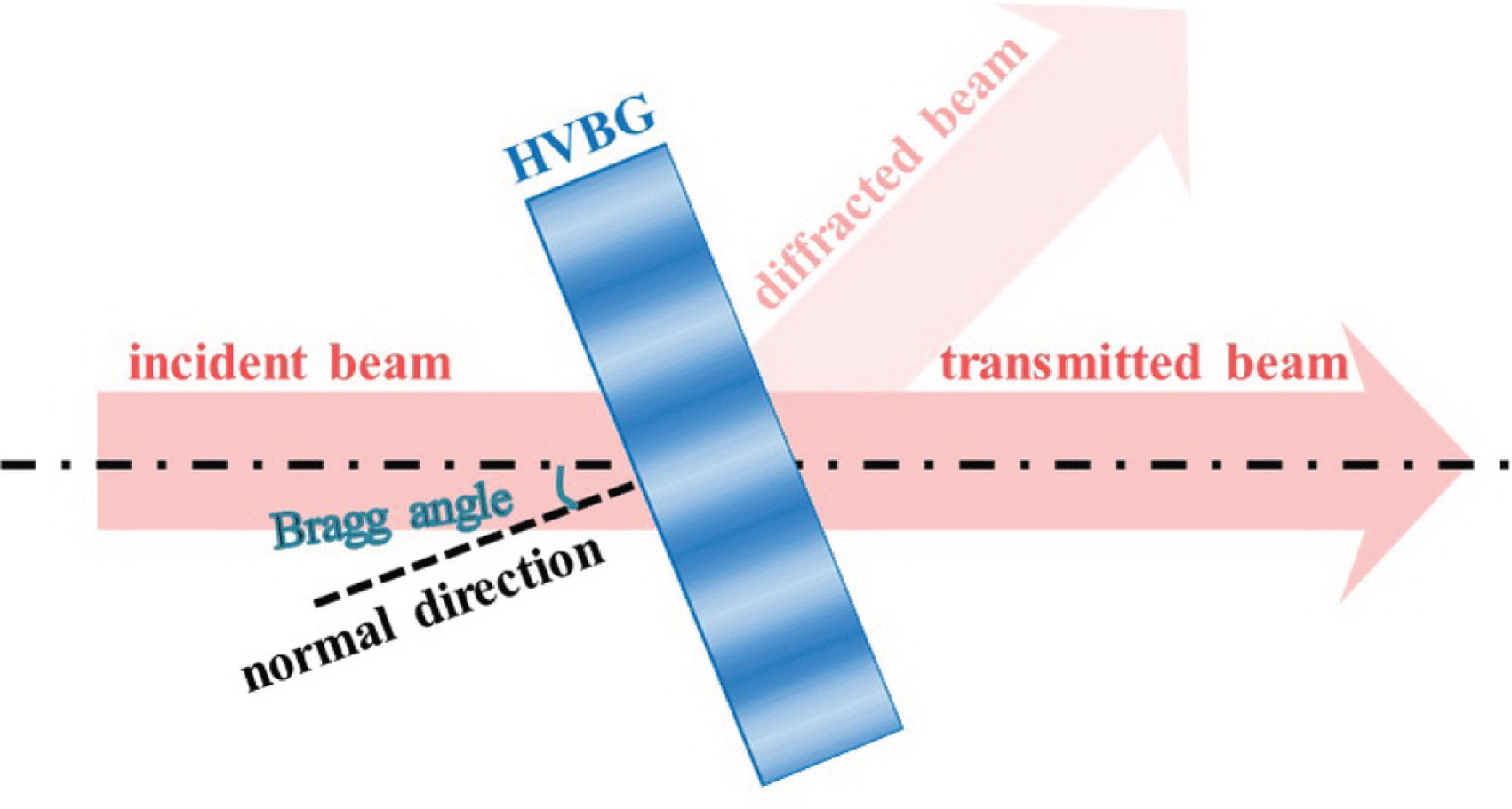
Figure 2. Principle of the BSF based on HVBGs.
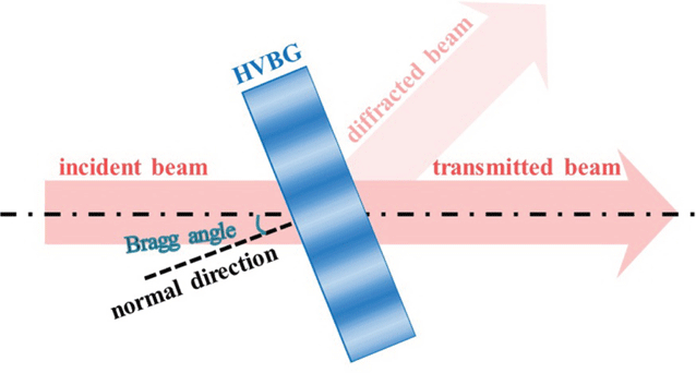
The filtering principle of the BSF based on HVBGs is shown in Figure 2. According to Fourier optics, an arbitrary laser beam can be considered as the superposition of an infinite number of monochromatic plane waves with different propagation directions, which represent different spatial frequencies. The intensity and phase distribution of the laser beam determine its spatial frequency distribution following Fourier transformation. The HVBG has a special angular selectivity, as shown in Figure 1(b), that can be used to achieve the separation of specific MHFs and other spatial frequencies in the laser beam. When the laser beam is incident on the HVBG at the Bragg angle, only the specific MHFs corresponding to the two hump peaks will be diffracted, and most frequency components of the incident laser beam will be transmitted through the HVBG, realizing the band-stop angular filtering.
In this regime, the transmitted beam is regarded as the filtered output beam of the BSF based on HVBGs, and the optical axis of the filtered beam is coaxial with that of the incident beam, thus allowing its use in plug-and-play schemes in laser systems. Furthermore, since the interval between the hump peaks can be tuned by controlling the grating parameters, the spatial frequencies of the incident laser beam filtered by HVBGs can be adjusted, allowing its use in laser systems to control the growth of specific MHFs that may have large nonlinear gain and to suppress the SSSF effects.
3 Model and algorithm for the simulation of band-stop filtering
The simulation model of band-stop filtering based on HVBGs in a two-stage amplifier laser system is shown in Figure 3. The laser system consists of two identical amplifiers, with each amplifier including five slabs of Nd-doped phosphate glass mounted at the Brewster angle. The laser slabs are
![]() $116~\text{mm}\times 116~\text{mm}\times 41~\text{mm}$
in size with a nonlinear refractive index of
$116~\text{mm}\times 116~\text{mm}\times 41~\text{mm}$
in size with a nonlinear refractive index of
![]() $n_{2}=1.02\times 10^{-13}$
esu, a small-signal gain coefficient of
$n_{2}=1.02\times 10^{-13}$
esu, a small-signal gain coefficient of
![]() $g_{0}=0.05~\text{cm}^{-1}$
and a saturated fluence of about
$g_{0}=0.05~\text{cm}^{-1}$
and a saturated fluence of about
![]() $4.84~\text{J}/\text{cm}^{2}$
. Two orthogonal HVBGs are inserted between the two amplifiers to realize two-dimensional band-stop filtering. They are designed to filter the MHFs at around
$4.84~\text{J}/\text{cm}^{2}$
. Two orthogonal HVBGs are inserted between the two amplifiers to realize two-dimensional band-stop filtering. They are designed to filter the MHFs at around
![]() $1.0~\text{mm}^{-1}$
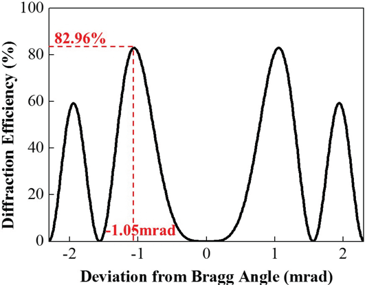
(corresponding to a deviation of 1.05 mrad from the Bragg angle), which possess the fastest nonlinear growth rate in this laser system. The two HVBGs have the same structural parameters, as listed in Table 1, and the angular selectivity is shown in Figure 4. The HVBGs in this Letter are designed with an average refractive index of 1.5.
$1.0~\text{mm}^{-1}$
(corresponding to a deviation of 1.05 mrad from the Bragg angle), which possess the fastest nonlinear growth rate in this laser system. The two HVBGs have the same structural parameters, as listed in Table 1, and the angular selectivity is shown in Figure 4. The HVBGs in this Letter are designed with an average refractive index of 1.5.

Figure 3. Diagram of band-stop filtering in a two-stage amplifier system.
Table 1. Parameters of the HVBGs used in the simulation.
PDE represents the peak diffraction efficiency; HWFM represents the half-width of the first maximum point, corresponding to half the interval between the hump peaks of the HVBGs.

Figure 4. Angular selectivity of the HVBGs used in the simulation.
The intensity distribution of the incident laser beam used in the simulation is shown in Figure 5(a), with an average power density of
![]() $2.27~\text{GW}/\text{cm}^{2}$
, a pulse duration of 3.5 ns and a beam size of
$2.27~\text{GW}/\text{cm}^{2}$
, a pulse duration of 3.5 ns and a beam size of
![]() $40~\text{mm}\times 40~\text{mm}$
at a wavelength of 1053 nm. The incident laser beam is modulated only in intensity, and no other source of spatial or phase noise is introduced in the amplifier system. To illustrate the effect of band-stop filtering, the incident laser beam is propagated through the two-stage amplifier system both without BSF and with BSF, respectively. To evaluate the laser beam propagation in nonlinear media, the break-up integral (B integral) is used to characterize the accumulated beam break-up[Reference Bespalov and Talanov2] and the near-field modulation (
$40~\text{mm}\times 40~\text{mm}$
at a wavelength of 1053 nm. The incident laser beam is modulated only in intensity, and no other source of spatial or phase noise is introduced in the amplifier system. To illustrate the effect of band-stop filtering, the incident laser beam is propagated through the two-stage amplifier system both without BSF and with BSF, respectively. To evaluate the laser beam propagation in nonlinear media, the break-up integral (B integral) is used to characterize the accumulated beam break-up[Reference Bespalov and Talanov2] and the near-field modulation (
![]() $M$
) is used to assess the development of SSSF. For high-power laser systems, the requirement of near-field modulation in the laser beam is typically
$M$
) is used to assess the development of SSSF. For high-power laser systems, the requirement of near-field modulation in the laser beam is typically
![]() $M<1.5$
[Reference Henesian, Renard, Auerbach, Caird, Ehrlich, Haney, Hunt, Lawson, Manes, Milam, Sacks, Seppala, Smith, Speck, Thompson, Van Wonterghem, Wegner, Weiland, Widmayer, Williams and Trenholme23].
$M<1.5$
[Reference Henesian, Renard, Auerbach, Caird, Ehrlich, Haney, Hunt, Lawson, Manes, Milam, Sacks, Seppala, Smith, Speck, Thompson, Van Wonterghem, Wegner, Weiland, Widmayer, Williams and Trenholme23].
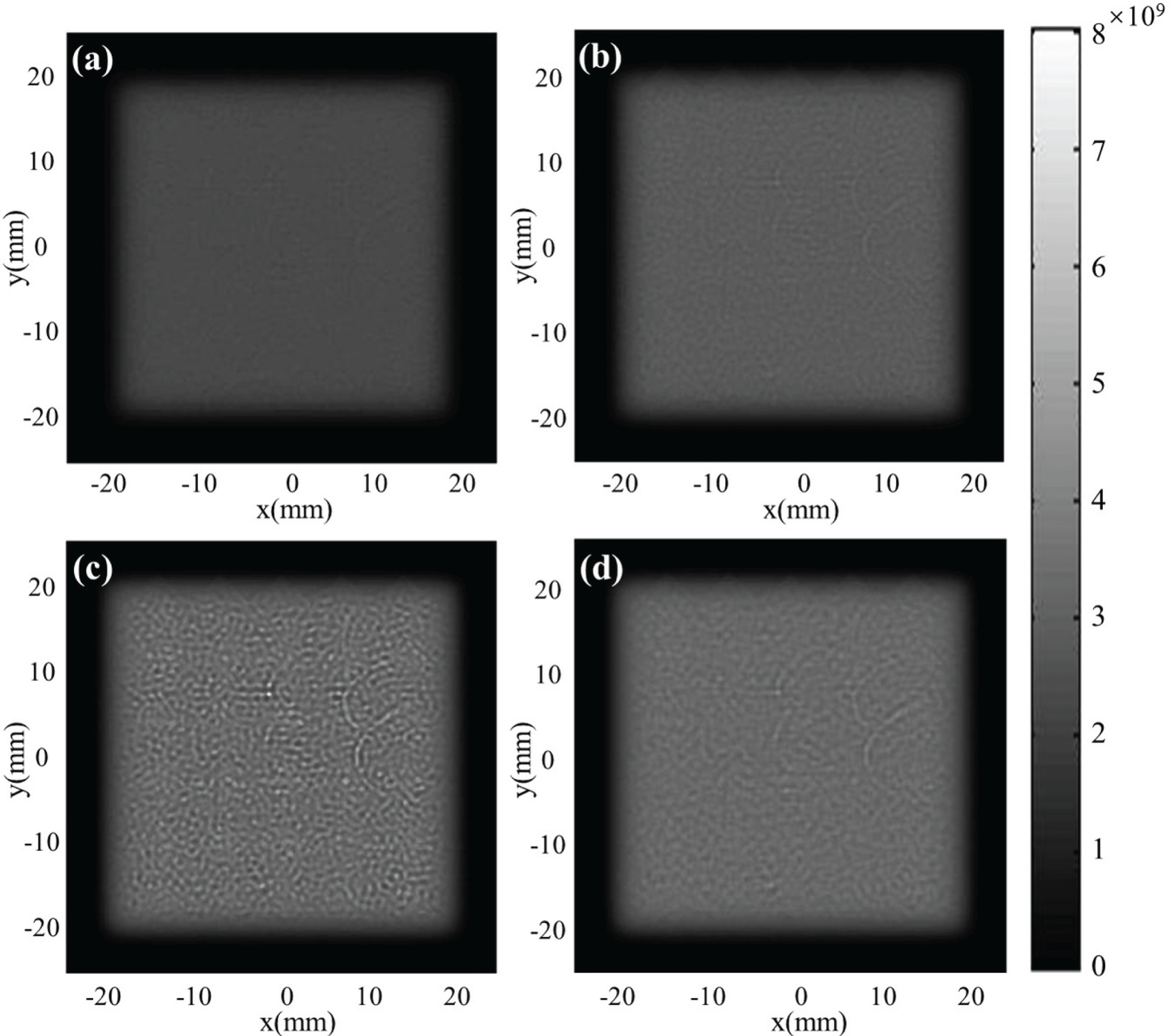
Figure 5. Near-field beam profiles of (a) the incident beam, (b) output beam from Amp.1, and output beams from the two-stage amplifier system (c) without BSF and (d) with BSF.
The simulation involves laser beam propagation in free space and laser slabs. The fast Fourier transform (FFT) based angular spectral method[Reference Simmons, Hunt and Warren24] is used to simulate the propagation in free space. For propagation in the laser slabs, three effects – diffraction, amplification and nonlinearity – are considered in this Letter. In this case, the propagation of an intense laser beam can be described with the following nonlinear paraxial wave equation[Reference Fleck, Morris and Bliss25]:
where
![]() $k_{0}=2\unicode[STIX]{x03C0}n_{0}/\unicode[STIX]{x1D706}$
,
$k_{0}=2\unicode[STIX]{x03C0}n_{0}/\unicode[STIX]{x1D706}$
,
![]() $n_{0}$
is the linear refractive index,
$n_{0}$
is the linear refractive index,
![]() $U$
is the slowly varying part of the electric field, normalized to the intensity
$U$
is the slowly varying part of the electric field, normalized to the intensity
![]() $I=UU^{\ast }$
,
$I=UU^{\ast }$
,
![]() $n_{2}I$
represents the nonlinear part of the refractive index through the relation
$n_{2}I$
represents the nonlinear part of the refractive index through the relation
![]() $n=n_{0}+4\unicode[STIX]{x03C0}n_{2}I\times 10^{7}/c~n_{0}\langle \text{CGSE}\rangle$
,
$n=n_{0}+4\unicode[STIX]{x03C0}n_{2}I\times 10^{7}/c~n_{0}\langle \text{CGSE}\rangle$
,
![]() $\unicode[STIX]{x1D6FC}$
is the loss coefficient,
$\unicode[STIX]{x1D6FC}$
is the loss coefficient,
![]() $\unicode[STIX]{x1D6FD}=\ln G/z$
is the gain coefficient, and
$\unicode[STIX]{x1D6FD}=\ln G/z$
is the gain coefficient, and
![]() $G$
is the gain of the nonlinear medium, which can be obtained from the Frantz–Nodvik equation[Reference Frantz and Nodvik26]:
$G$
is the gain of the nonlinear medium, which can be obtained from the Frantz–Nodvik equation[Reference Frantz and Nodvik26]:
where
![]() $g_{0}=\exp (\unicode[STIX]{x1D6FD}_{0}z)$
is the small-signal gain,
$g_{0}=\exp (\unicode[STIX]{x1D6FD}_{0}z)$
is the small-signal gain,
![]() $\unicode[STIX]{x1D6FD}_{0}$
is the small-signal gain coefficient,
$\unicode[STIX]{x1D6FD}_{0}$
is the small-signal gain coefficient,
![]() $w_{\unicode[STIX]{x1D70F}}=\int _{0}^{\unicode[STIX]{x1D70F}}I_{\text{in}}(0,t)/E_{s}\,\text{d}t$
is the accumulated energy injection during the time period from 0 to
$w_{\unicode[STIX]{x1D70F}}=\int _{0}^{\unicode[STIX]{x1D70F}}I_{\text{in}}(0,t)/E_{s}\,\text{d}t$
is the accumulated energy injection during the time period from 0 to
![]() $\unicode[STIX]{x1D70F}$
,
$\unicode[STIX]{x1D70F}$
,
![]() $I_{\text{in}}(0,t)$
is the input intensity, and
$I_{\text{in}}(0,t)$
is the input intensity, and
![]() $E_{s}$
is the saturation fluence of the nonlinear medium, which is about
$E_{s}$
is the saturation fluence of the nonlinear medium, which is about
![]() $4.68~\text{J}/\text{cm}^{2}$
for the Nd-doped phosphate glass.
$4.68~\text{J}/\text{cm}^{2}$
for the Nd-doped phosphate glass.
Laser beam propagation in the laser slabs is simulated by solving Equation (3) with the split-step Fourier method (SSFM), which is a commonly used numerical algorithm. By SSFM, the propagation through the laser slabs is divided into a number of steps with equal length
![]() $\unicode[STIX]{x1D6FF}z$
. The diffraction, amplification and nonlinearity are calculated independently in each step, and the analytical solutions of different effects can be obtained individually[Reference Taha and Ablowitz27].
$\unicode[STIX]{x1D6FF}z$
. The diffraction, amplification and nonlinearity are calculated independently in each step, and the analytical solutions of different effects can be obtained individually[Reference Taha and Ablowitz27].
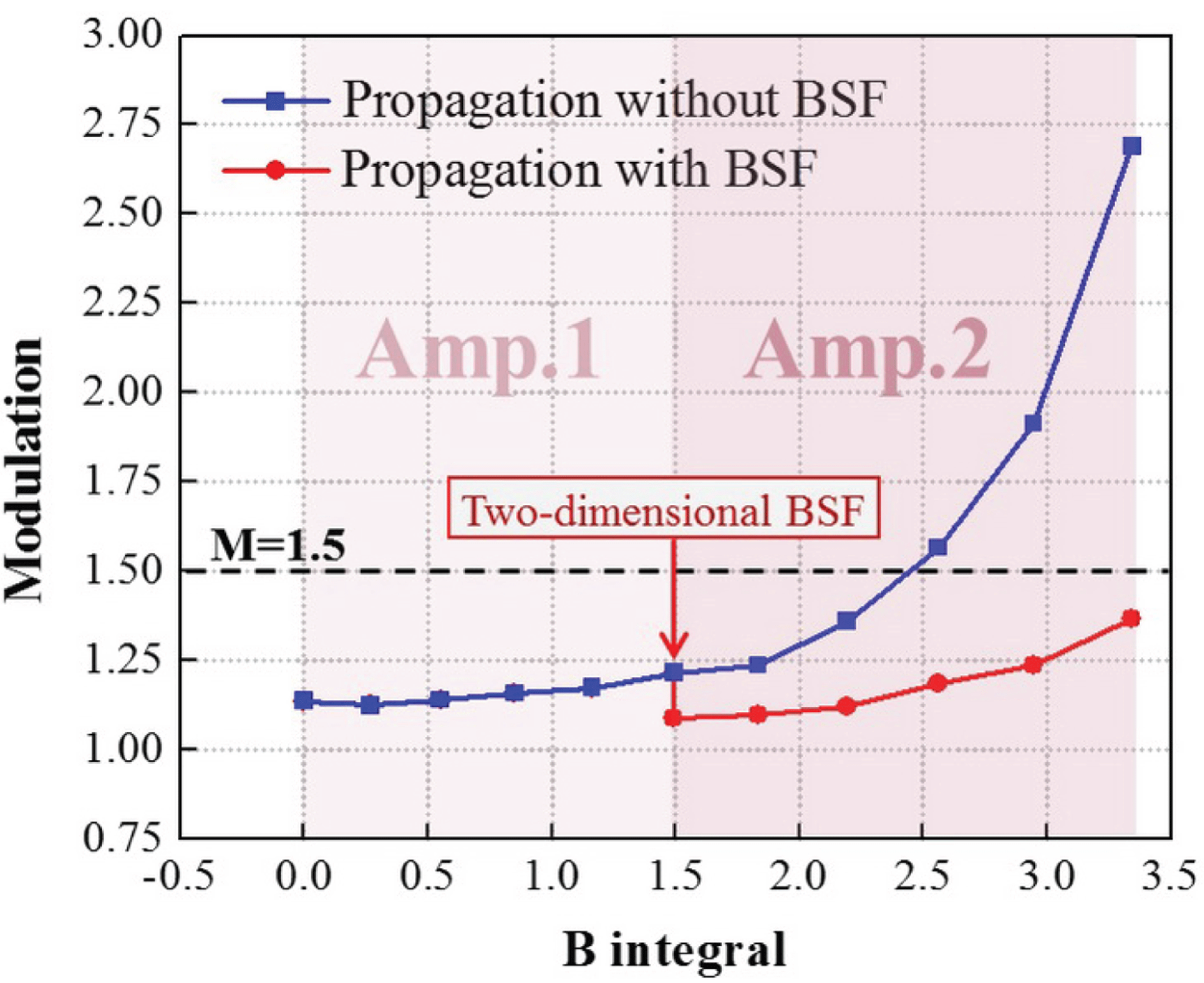
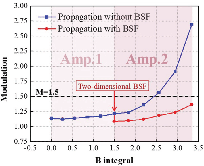
Figure 6. The dependence of near-field modulation on the accumulated B integral.
4 Results and discussions
The following results are obtained in the simulation. As the incident laser beam propagates through Amp.1, the near-field intensity distribution of the beam gets worse, as shown in Figure 5(b). The accumulated B integral increases to 1.49 and the near-field modulation of the beam increases from 1.14 to 1.21, as shown in Figure 6. Since the nonlinear growth in Amp.1 is not serious, the near-field modulation of the laser beam still keeps at a relatively low value and satisfies the limitation of 1.5 for high-power lasers.
As the laser beam continues to propagate through Amp.2, the accumulated B integral of the beam reaches 3.34. Allowing the output beam from Amp.1 to directly propagate through Amp.2 without filtering, localized and extremely high-intensity modulation appears in the near-field profile of the laser beam, indicating the occurrence of SSSF, as shown in Figure 5(c). The near-field modulation of the laser beam increases sharply from 1.21 to 2.69, as shown by the blue line in Figure 6. The beam quality of the output beam from the two-stage amplifier system is severely degraded. On the other hand, if the output beam from Amp.1 is two-dimensional band-stop filtered, the near-field modulation of the laser beam decreases from 1.21 to 1.09. With further propagation through Amp.2, the near-field modulation of the laser beam increases with a slow growth rate, and the modulation of output beam reaches only 1.37, as shown by the red line in Figure 6. In addition, the near-field intensity distribution of the output beam is greatly improved, as shown in Figure 5(d).
It can be seen from Figure 6 that when the incident laser beam propagates through the two-stage amplifier system without filtering, modulation of the laser beam increases rapidly in Amp.2, and exceeds the limitation of 1.5 as the B integral reaches about 2.5. Whereas if the BSF is inserted between the two amplifiers, growth of the near-field modulation of the laser beam in Amp.2 is slowed and the modulation is less than 1.5 even if the accumulated B integral reaches 3.34. Consequently, once the spatial frequencies around
![]() $1~\text{mm}^{-1}$
are removed with the two-dimensional BSF, the SSSF effect in the output beam from the two-stage amplifier laser system can be suppressed and the beam quality can be improved.
$1~\text{mm}^{-1}$
are removed with the two-dimensional BSF, the SSSF effect in the output beam from the two-stage amplifier laser system can be suppressed and the beam quality can be improved.
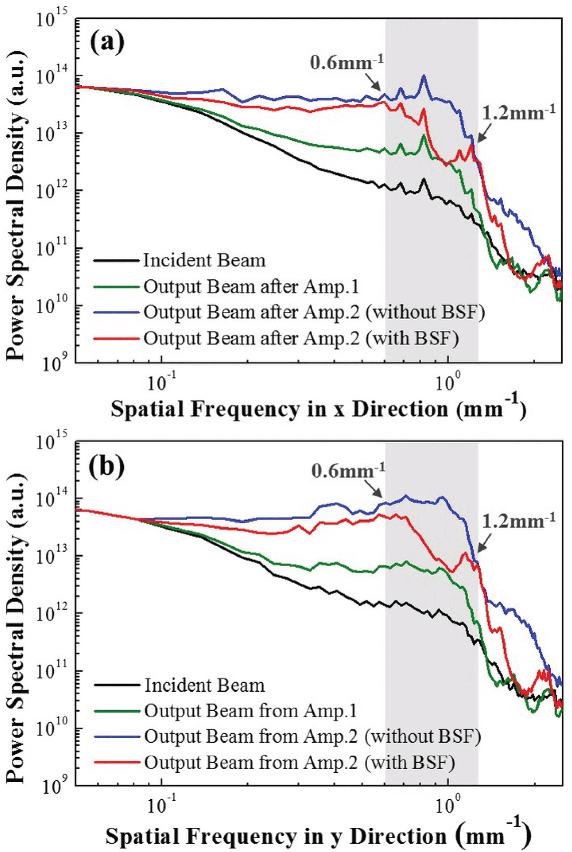
Figure 7. Dependence of the normalized PSD on the spatial frequency both in (a) the
![]() $x$
direction and (b) the
$x$
direction and (b) the
![]() $y$
direction for the incident beam, the output beam from Amp.1 and the output beams from the two-stage amplifier system without and with two-dimensional BSF.
$y$
direction for the incident beam, the output beam from Amp.1 and the output beams from the two-stage amplifier system without and with two-dimensional BSF.
The PSD function is used to analyze the laser beam in the frequency domain and evaluate the band-stop filtering effect. Figure 7 shows the dependence of the PSD on spatial frequency for the incident and output beams of the two-stage amplifier laser system. Compared to the incident beam (black curve in Figure 7), the PSD in the spatial frequency range from 0.2 to
![]() $1.3~\text{mm}^{-1}$
is increased after propagation in Amp.1, as shown by the green curve in Figure 7. With further propagation in Amp.2, the PSD in a wider range of spatial frequencies from 0.11 to
$1.3~\text{mm}^{-1}$
is increased after propagation in Amp.1, as shown by the green curve in Figure 7. With further propagation in Amp.2, the PSD in a wider range of spatial frequencies from 0.11 to
![]() $2.1~\text{mm}^{-1}$
is increased due to nonlinear and diffraction effects, as shown by the blue curve in Figure 7. We can see that spatial frequencies from 0.6 to
$2.1~\text{mm}^{-1}$
is increased due to nonlinear and diffraction effects, as shown by the blue curve in Figure 7. We can see that spatial frequencies from 0.6 to
![]() $1.2~\text{mm}^{-1}$
exhibit the fastest nonlinear growth both in the
$1.2~\text{mm}^{-1}$
exhibit the fastest nonlinear growth both in the
![]() $x$
and
$x$
and
![]() $y$
directions after the two-stage amplification. As the two-dimensional BSF with HVBGs is inserted into the system, the PSD in the spatial frequency range from 0.6 to
$y$
directions after the two-stage amplification. As the two-dimensional BSF with HVBGs is inserted into the system, the PSD in the spatial frequency range from 0.6 to
![]() $1.2~\text{mm}^{-1}$
is decreased substantially, as shown by the red curve in Figure 7. It can be concluded that fast nonlinear growth of specific MHFs around
$1.2~\text{mm}^{-1}$
is decreased substantially, as shown by the red curve in Figure 7. It can be concluded that fast nonlinear growth of specific MHFs around
![]() $1~\text{mm}^{-1}$
within the range from 0.6 to
$1~\text{mm}^{-1}$
within the range from 0.6 to
![]() $1.2~\text{mm}^{-1}$
in high-power laser systems can be effectively controlled by the BSF based on HVBGs.
$1.2~\text{mm}^{-1}$
in high-power laser systems can be effectively controlled by the BSF based on HVBGs.
In operation, the rapid growth of spatial frequencies around
![]() $1.0~\text{mm}^{-1}$
is based on a nonlinear accumulation process in the laser amplification. Band-stop filtering based on HVBGs arrests this accumulation before the rapid growth of spatial frequency occurs and can be used to suppress the SSSF, although it can filter only some specific spatial frequencies of laser beams.
$1.0~\text{mm}^{-1}$
is based on a nonlinear accumulation process in the laser amplification. Band-stop filtering based on HVBGs arrests this accumulation before the rapid growth of spatial frequency occurs and can be used to suppress the SSSF, although it can filter only some specific spatial frequencies of laser beams.
5 Conclusions
In summary, a BSF based on HVBGs was proposed and suppression of SSSF with a two-dimensional BSF was studied in a two-stage amplifier laser system. The B integral and the near-field modulation are used to assess the development of SSSF. As the incident beam propagates through the two-stage amplifier laser system, the accumulated B integral reaches 3.34. The near-field modulation of the laser beam increases from 1.14 to 2.69 and the SSSF effect is induced in the output beam. After the BSF based on two orthogonal HVBGs is inserted into the system, the near-field modulation of the output beam decreases from 2.69 to 1.37 and the SSSF effect is efficiently suppressed. The PSD curves indicate that spatial frequencies from 0.6 to
![]() $1.2~\text{mm}^{-1}$
possess the fastest nonlinear growth rates, both in the
$1.2~\text{mm}^{-1}$
possess the fastest nonlinear growth rates, both in the
![]() $x$
and
$x$
and
![]() $y$
directions, after propagating through the laser system, and can be effectively controlled with BSF. Since the BSF reduces only some specific MHFs in the laser beam, the insertion loss of BSF is low. In addition, the incident beam and the filtered beam are coaxial, which allows the BSF to be used in plug-and-play schemes and has potential applications in high-power laser systems.
$y$
directions, after propagating through the laser system, and can be effectively controlled with BSF. Since the BSF reduces only some specific MHFs in the laser beam, the insertion loss of BSF is low. In addition, the incident beam and the filtered beam are coaxial, which allows the BSF to be used in plug-and-play schemes and has potential applications in high-power laser systems.
Acknowledgements
This work was supported by the National Key R&D Program of China (No. 2016YFF0100903), the National Natural Science Foundation of China (NSFC) (Nos. 61775153, 61705153, and 11504255), the Natural Science Foundation of Jiangsu Province (No. BK20141232) and the Priority Academic Program Development of Jiangsu Higher Education Institutions (PAPD).


